GY500 Digital Gyro for RC Cars & Helis
Description:
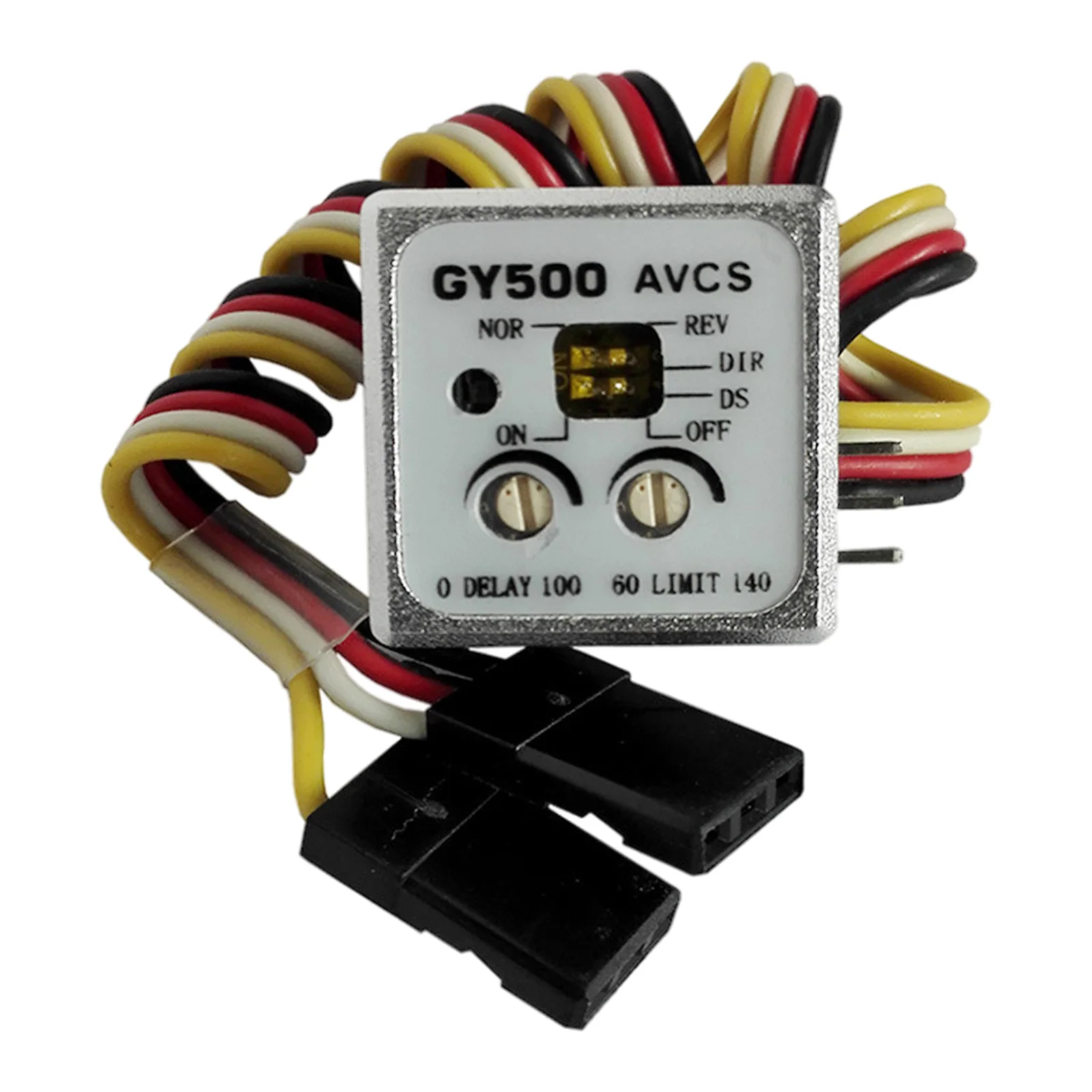
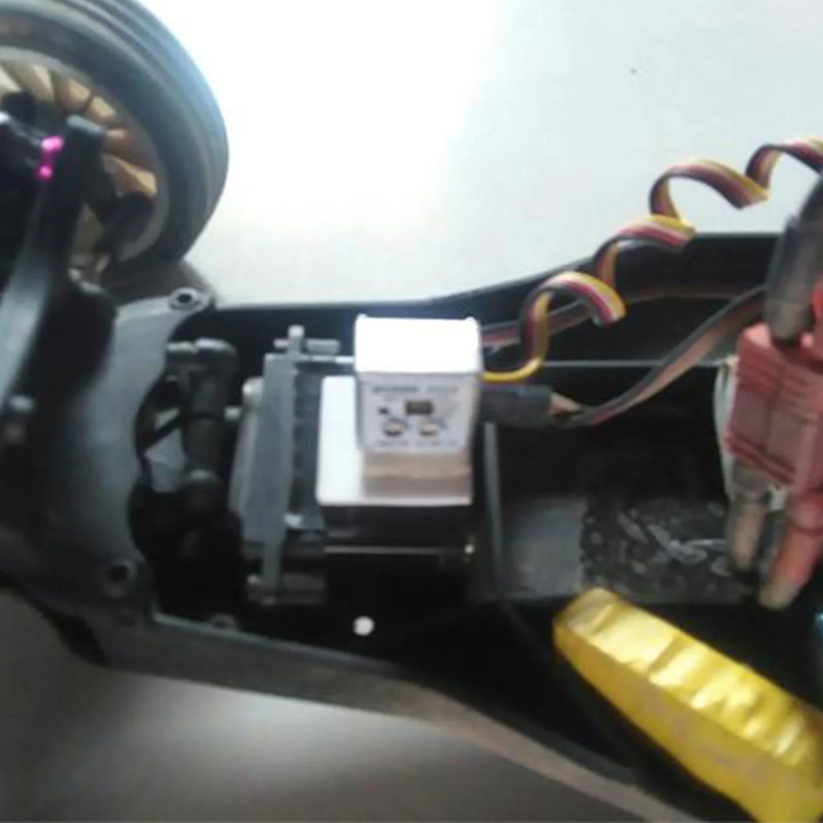
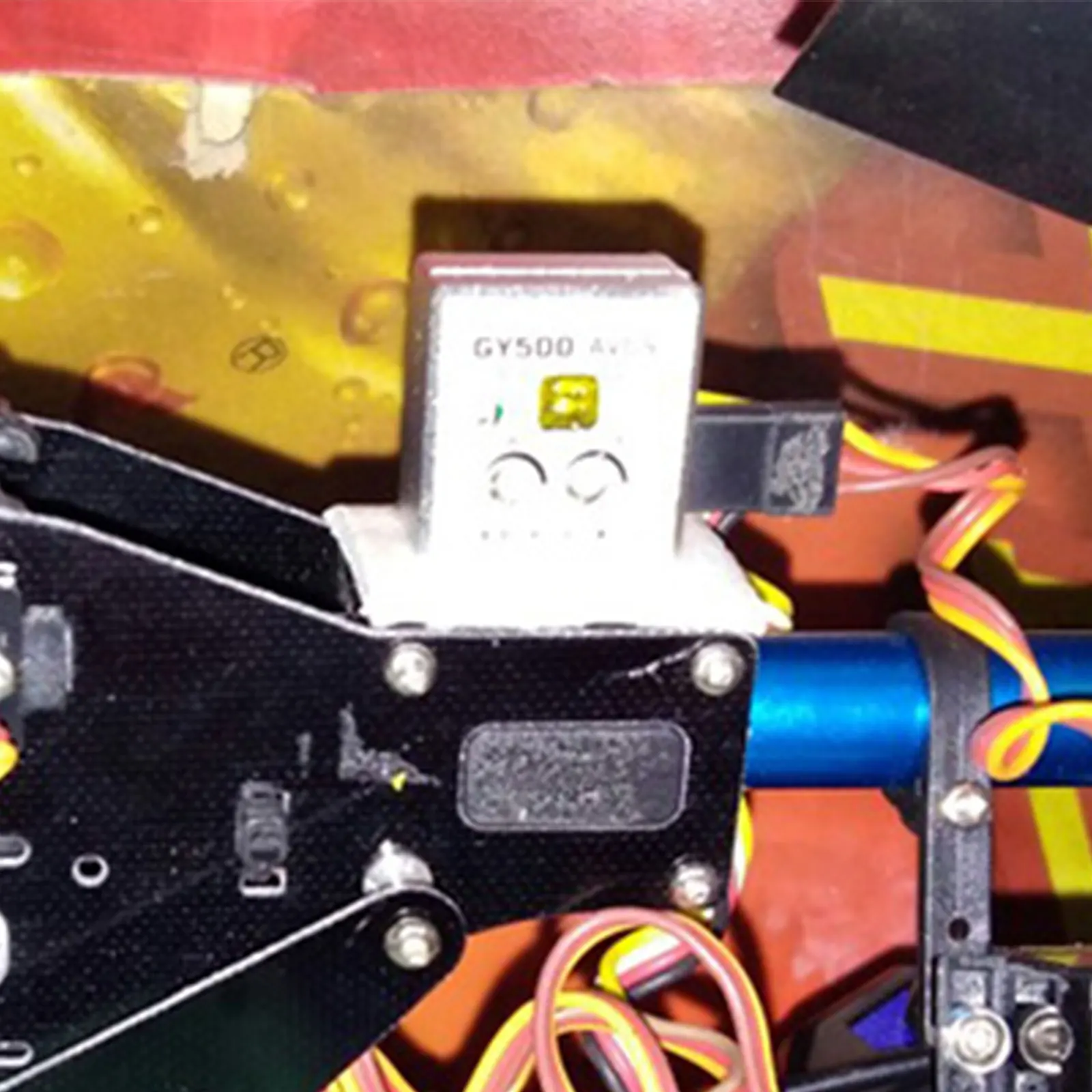
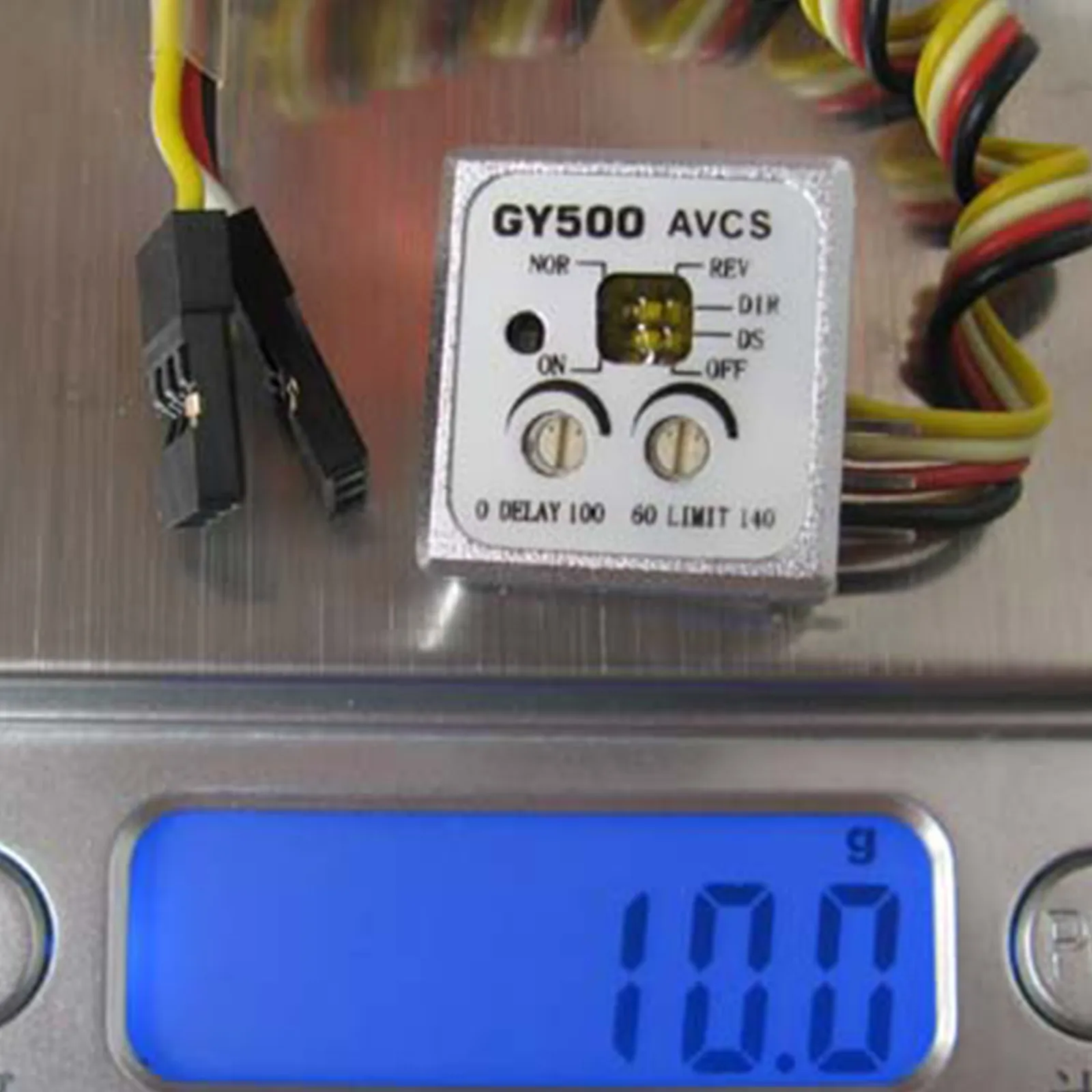
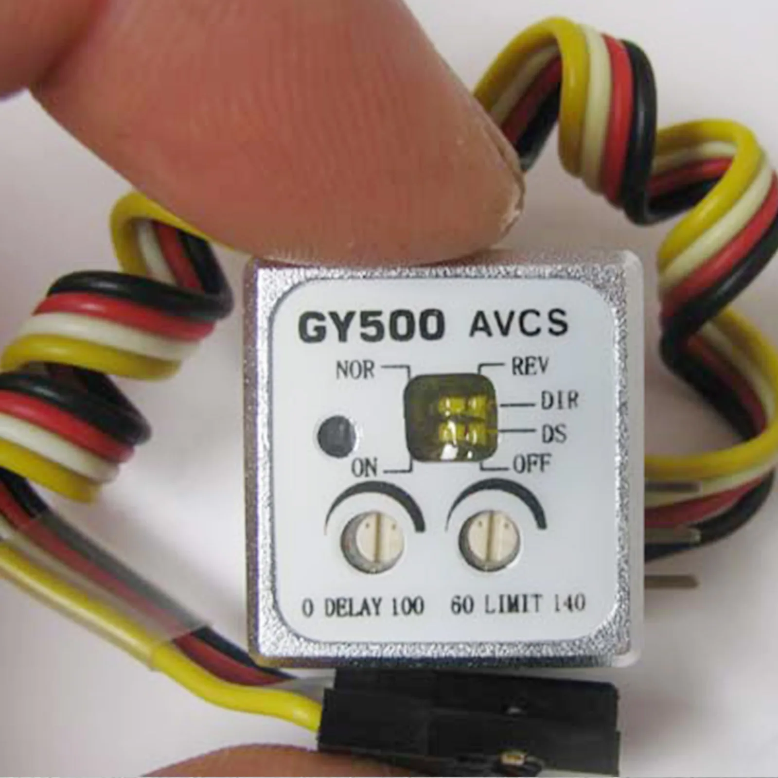
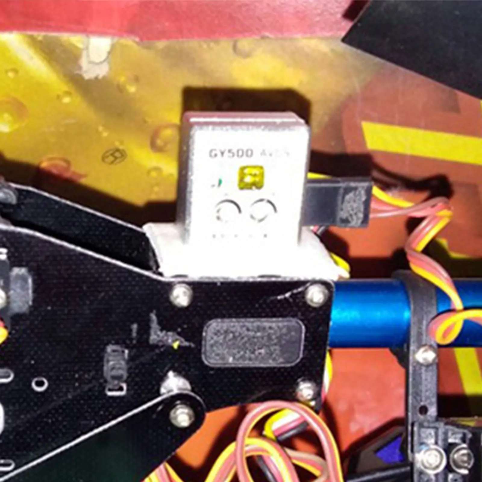
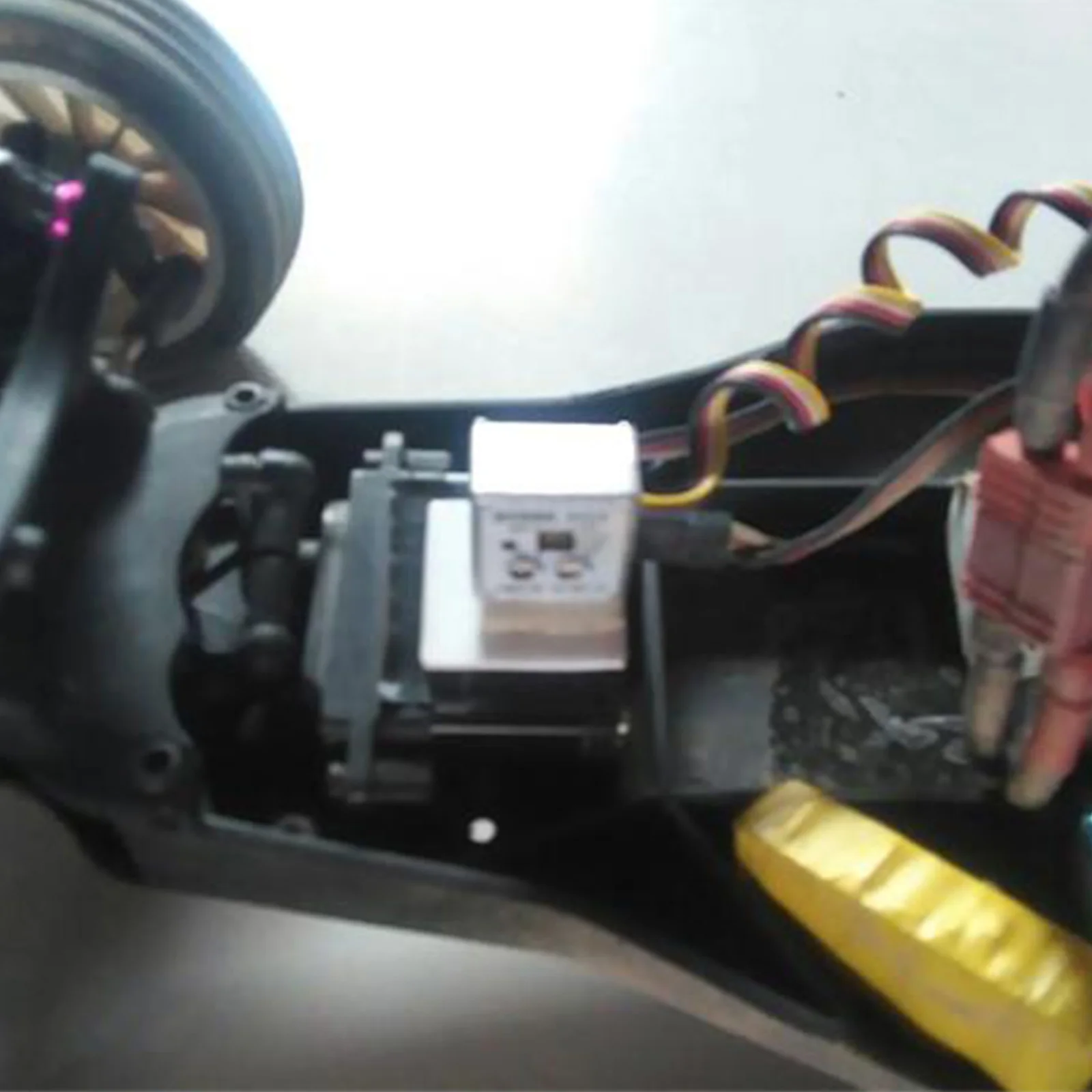
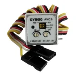
This product features a high-precision CNC-processed shell, which is both mini and lightweight. The housing is made from precision CNC-machined aluminum alloy, making it durable and robust. It is designed for use in car and boat locks, providing direction stability and anti-drift capabilities.
Model: GY500
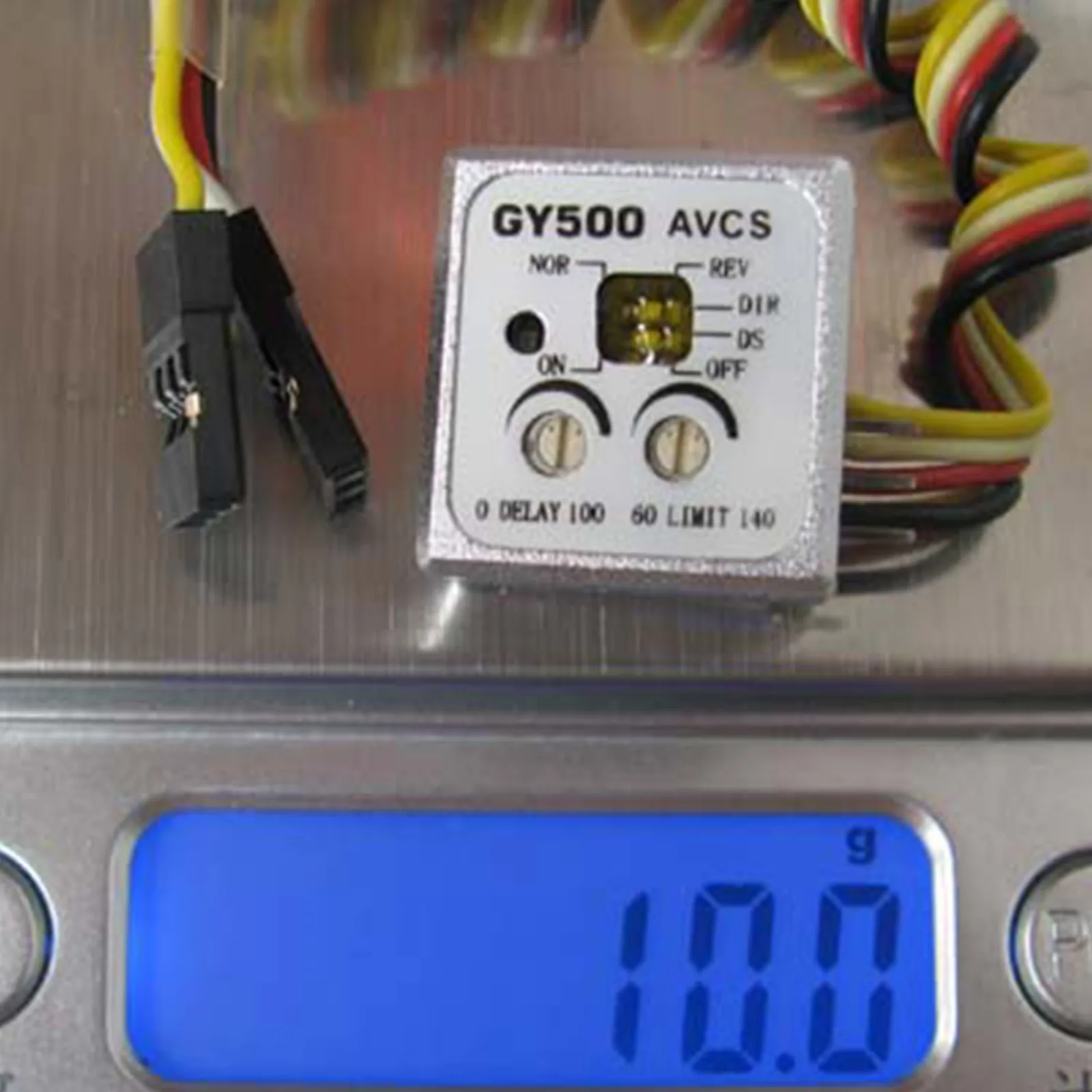
Size: The dimensions are 20×19×12mm.
Feature:
The gyroscope in this device is designed to counteract rudder deflection caused by crosswinds. It calculates the offset angle and sends continuous control signals to resist the wind. This ensures that even under continuous crosswind attacks, the rudder remains stable. The gyroscope automatically corrects tail rudder offsets caused by crosswinds. During helicopter rotation, the tail rudder swings according to the body’s angular velocity. When the rotation stops, the tail rudder automatically aligns to the correct stopping position. This is known as the automatic offset function.
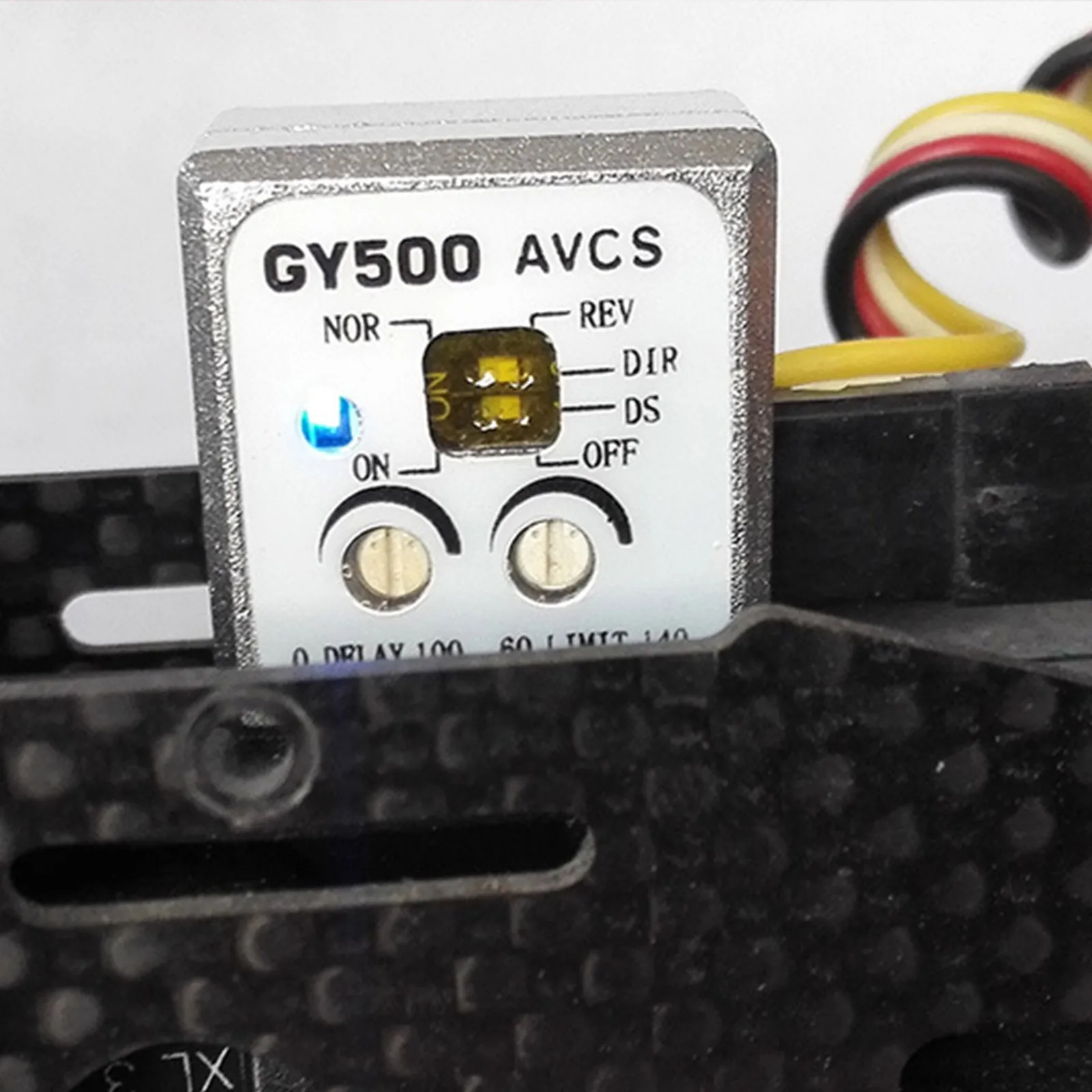
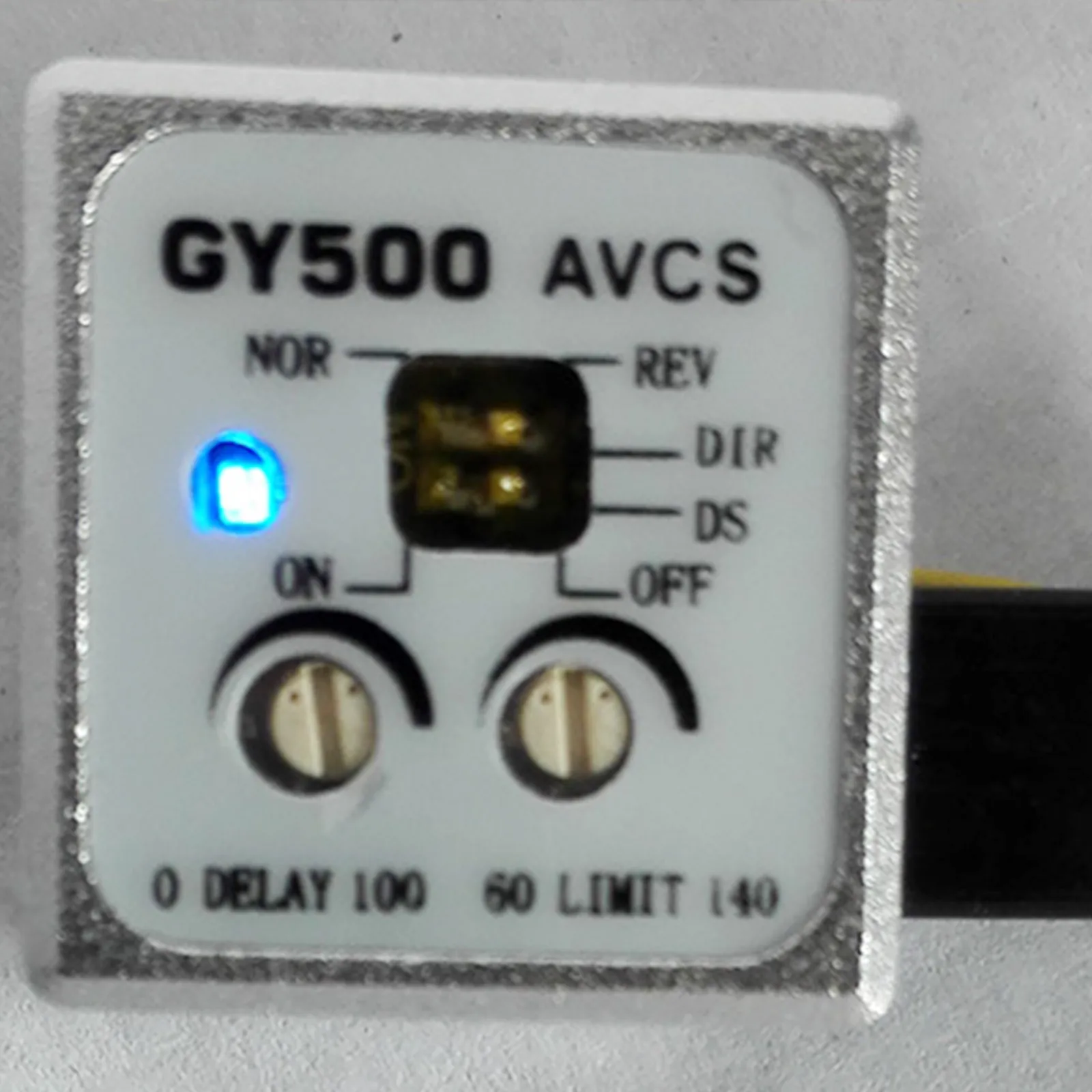
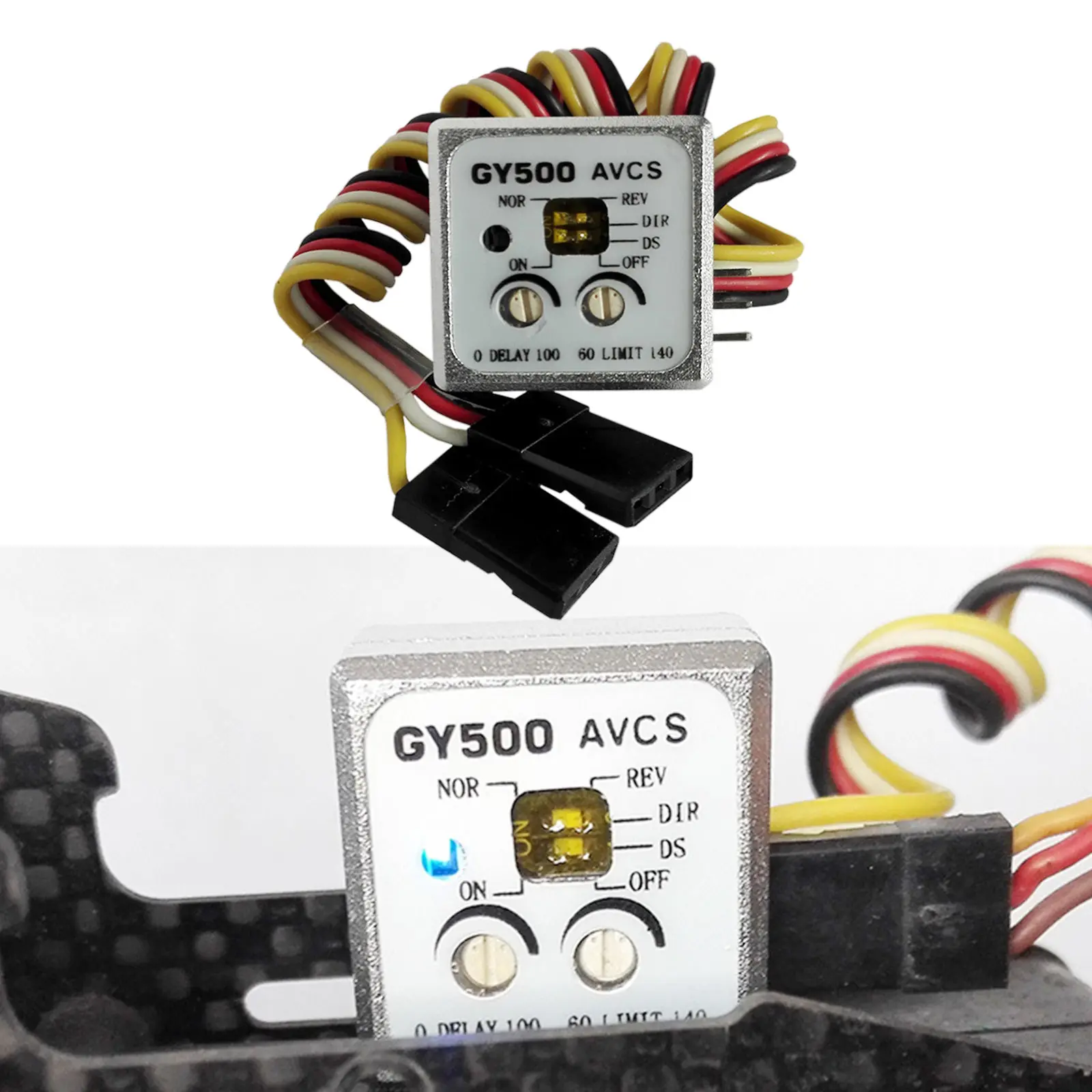
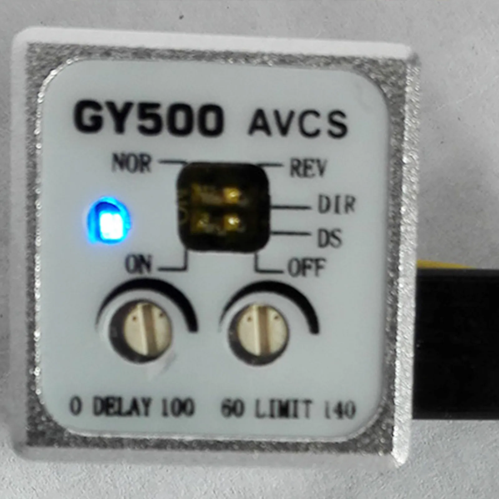
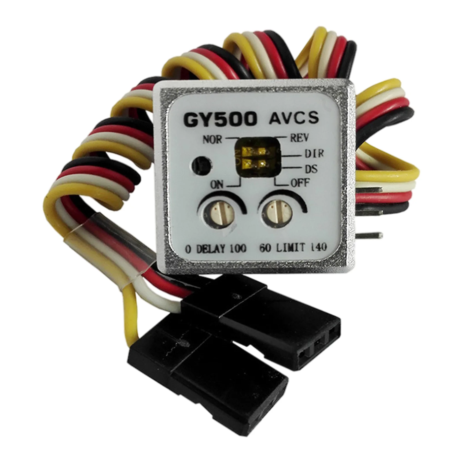
Reverse Switch: This switch changes the control direction of the gyroscope. It should be adjusted based on the rotation direction of the helicopter’s main rotor and the tail rudder link.
DS Mode Switch: This is a digital servo mode switch. When using a digital servo, switch it to the ON position. For general servos, switch it to OFF. Note: Incorrect positioning may cause servo damage due to different output signal formats.
Control Delay Adjustment Knob: This knob adjusts the operating speed of the tail control signal. To eliminate tracking issues with slower steering gears, turn the knob clockwise to increase delay time. For high-speed servos, like digital servos, set the knob to the 0 position.
Steering Gear Maximum Stroke Adjustment Knob: This sets the maximum stroke amount of the tail rudder servo. Adjust the knob while fully steering the rudder stick left and right, ensuring the stroke doesn’t exceed the tail pitch sleeve’s maximum range. Turn clockwise to increase the stroke.
Connection:
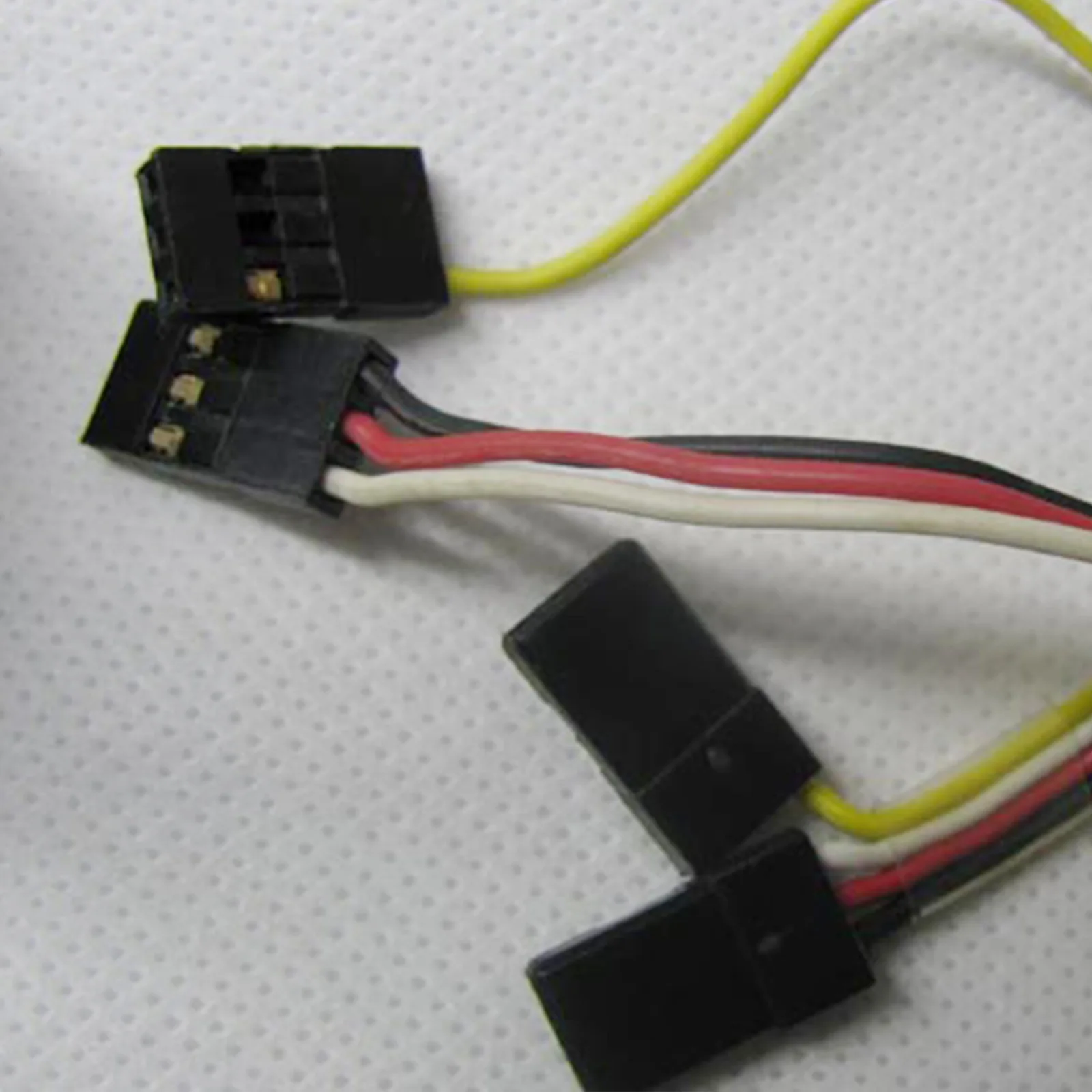
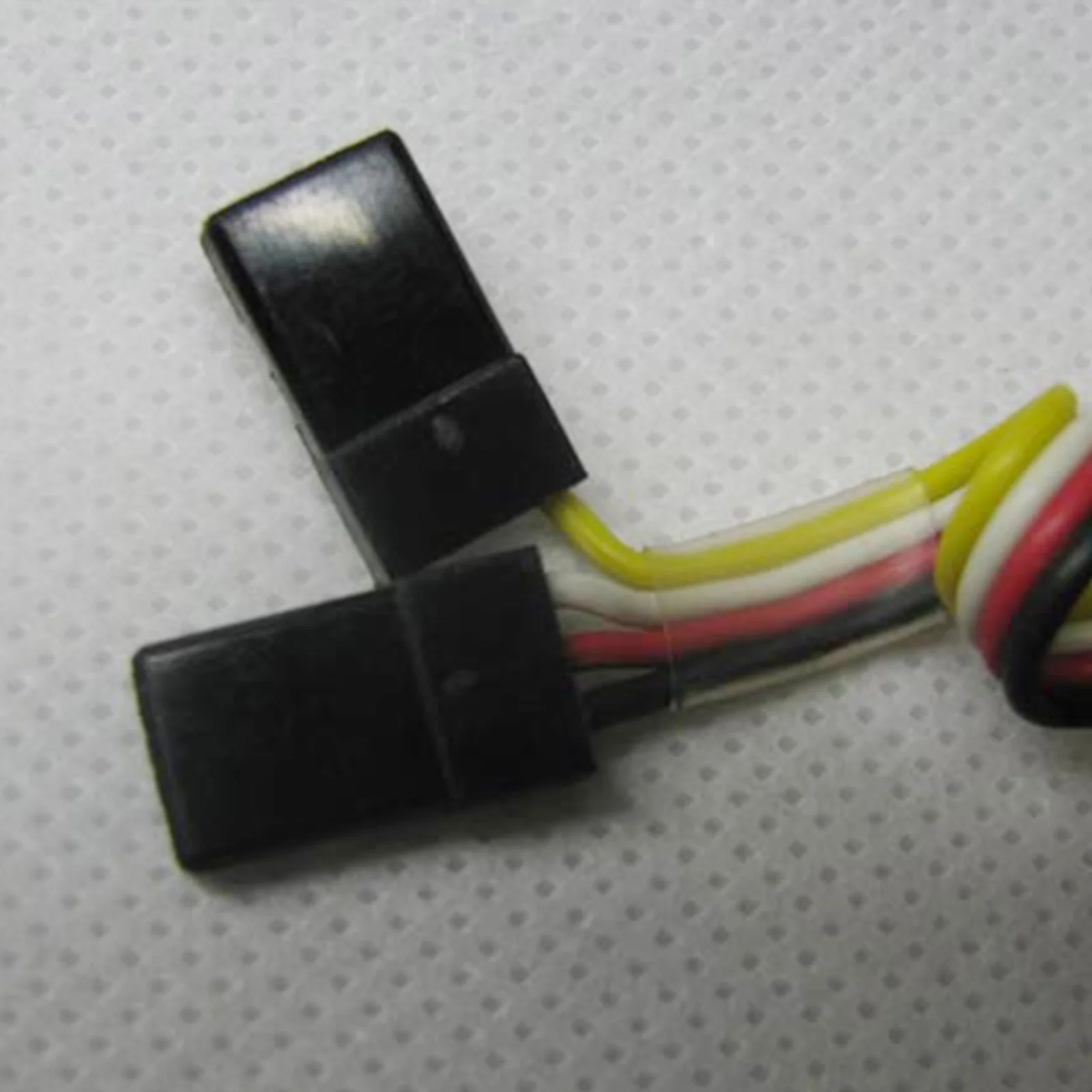
- Sensitivity Channel Interface: Connect to the receiver’s sensitivity channel (usually CH5). This allows simultaneous switching of the gyroscope’s sensitivity and mode (lock mode or general mode). Handle the single-core signal line connector carefully to prevent disconnection.
- Rudder Channel Interface: Connect to the receiver’s rudder channel (CH4).
- Tail Rudder Servo Interface: Connect to the tail rudder servo.
Function Instruction:
- For AVCS System: Automatically eliminates rudder offset due to wind or other factors, enhancing rudder control. Ideal for a 3D fancy flight.
- For Gyro Sensor: Features a new piezoelectric sensor to effectively reduce rudder offset during flight.
- For Digital Servo (DS Mode): Compatible with digital servos in DS mode, supporting high-speed response.
- For Remote Control: Allows adjustment of gyroscope sensitivity and switching between operation modes (lock mode or normal mode) via remote control.
Package Contents:
- 1x Gyro








There are no reviews yet.